
Description
VIBRO-LASER® ofers functionality and its high technical characteristics, making alignment process of your equipment (pump, electric motor, compression etc.) quick and exact, thus reducing its energy consumption and increasing service life.
Laser shaft alignment system VIBRO-LASER® advantages:
- Reducing energy consumption by 15% or more
- Reducing mechanic deterioration
- Reducing equipment vibration
- Increasing productivity
- Increasing overhaul interval
- Increasing equipment reliability
VIBRO-LASER® has an ergonomic design and is made of drop-impact materials.
This product offers an absolutely innovative, step-by-step, responsive interface with 3D-animation and
a wide eight-inch touch screen which simplifies the operator’s work and reduces the time of work.
Moreover, thanks to the unique memory management system you can stop the alignment, save the
current data and continue it anytime.
SENSOR UNITS
In the VIBRO-LASER® sensor units the latest digital and Bluetooth® data processing technology is used. Sensor units have CCD-detectors of 30 mm. This provides you with exact and stable measuring results and allows the system to be more interference-immune from the external factors (stray light, vibration, heat ow and etc.). Thanks to the compact and durable aluminum case of the sensor units, you can work even in the most confined space. Large CCD-detector also excludes ”rough alignment” system that significantly reduces the time of work.
Step 1: Following the dial indicator, step by step, make the alignment procedure.
Step 2: Based on the speed of the shaft, choose the required tolerance value.
Step 3: Enter necessary measurements by the virtual calculation.
Step 4: Enter necessary measurements by the virtual calculation. Make the measurements in any three points. When the shaft rotates, use the help of ”the information circle”.
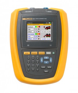
Step 5: Measurement results are displayed with the color indication: Green – value in tolerance; Yellow- value within double tolerance; Red – value out of tolerance.
Step 6: When the system aligns, it tracks the position of the machine online and automatically advises,
where and how far to remove it to get the required tolerance value