
Description
Features:
- Mains filter for direct coupling to live cables up to 660 V
- Pulsed output current for easier detection of the test signal
- Filter for the suppression large interference signals
- Location of earth faults up to 150 kOhm
- No switch off during the fault location required
- No influence to the signal lines connected to
Specially protected IT networks, such as those found in hospitals, are designed in such a way that any contact with a
voltage carrying line is harmless; in the event of a short to earth, explosion protection reduces current ow to zero.
Important control, signal and supply systems, such as those for railway installations, power plants or other industrial facilities, are designed to be potential-free and are monitored by earth fault indicators in order to ensure safe and uninterrupted operation.
Short-to-ground faults in IT networks, control lines or, for example, signal lines in railways are referred to as earth
faults.
While a single earth fault will not disrupt the service, a second earth fault carries a high risk of partial or complete installation breakdown. For this reason, any earth fault must be located and repaired as fast as possible.
The start point of a feeding transformer in an IT network is not grounded, and the protective earth of the load is separately grounded.
In industrial systems where cables are frequently in highly conductive environments, a short-circuit is one of the greatest potential hazards.
While a ground fault in an IT network won’t initially trip any fuses or interrupt any processes, the short will cause the formerly unearthed, potential-free system to set itself to the earth potential created by the fault.
As a consequence, the unaffected phases take up a defined potential against the earth.
An additional short of a different phase (double earth fault) can now cause a true short-circuit, resulting in the total failure of the electrical system. Such a failure could stop critical manufacturing processes or create an arc due to high current flow, posing great danger in an explosion-protected environment.
Such installations have an insulation or earth fault monitoring system, which displays this state in the event of a earth fault, thus warning the operator.
The operator must localise and resolve this earth fault as fast
as possible in order to restore the operating safety of the
system.
One of the easiest and fastest options for localising these earth faults is the Geolux System.
The idea behind the technology used in the Geolux is to locate the earth fault without interrupting supply or affecting
the data and control circuits. In the Geolux system, a low frequency signal current of 5 Hz is galvanically coupled to
the conductor with the earth fault.
The integrated separation filter enables a direct galvanic
coupling of up to 660 V AC and DC.
Inductive sensors trace the signal current’s electromagnetic field and guide the user to the fault position. A pulse is used to better identify the signal current. The signal pulse of the generator is synchronised with the receiver and displayed accordingly.
A circuit in the receiver and clamp compensates for the interfering cable capacities, allowing fault resistances of up to
200 kOhm to be localised.
The operator follows the path of the signal current to the earth fault using inductive signal clamps (or an inductive
contact sensor where cable bundling does not permit this). When the signal divides and can no longer be traced, he has found the earth fault.
| TECHNICAL DATA* | |
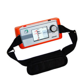
| Receiver GLE 660-1 | |
| Amplification | 70 dB … 100 dB |
| Filter | 16.66 and 50 Hz Notch |
| Power Supply | 8 x 1.5 V AA batteries (LR 6) |
| Operating Time | approx. 40 hours |
| Operating Temperature | – 10 _C … + 50 _C |
| Storage Temperature | – 25 _C … + 70 _C |
| Max. rel. humidity | < 80 % |
| Weight | approx. 1.2 kg |
| Dimensions (W x H x D) | 220 mm x 100 mm x 130 mm |
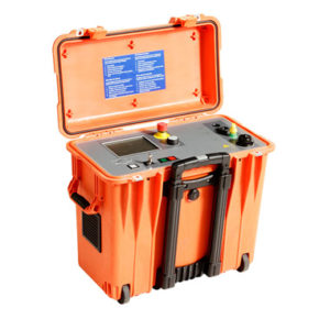
| Transmitter GLE 660-1 | |
| Power Supply | Mains 230 V, 45 … 60 Hz
Battery (rechargeable) 12 V / 2,4 Ah |
| Operating time at 80 V | approx. 5 h |
| Transmitter frequency | 5 Hz +/- 0.1 Hz |
| Externel dielectric strength | 660 V AC/DC |
| Operating Temperature | – 10 _C … + 50 _C |
| Storage Temperature | – 25 _C … + 70 _C |
| Weight | approx. 12 kg |
| Dimensions (W x H x D) | 366 mm x 183 mm x 260 mm |
Standard Accessories
■ Reader clamps AZK 100, 100 mm, compensated
■ Hight voltage cable HSK 7-B
■ Connection cable VK 50, 10 m
■ Probe for round conductor GSK 1
■ Reader clamp AZK 12, 12 mm
Special Accessories
■ Cable drum for compensation KTG 50, 50 m
■ Probe for earth cable GS 5